

|
|
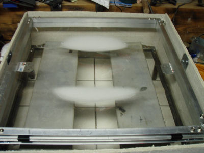
Late September last year, I started experimenting by forming styrene light fixture panels around Styrofoam patterns.
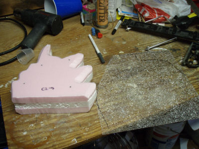 Three sheets of styrofoam and the styrene I thought I could mold on top
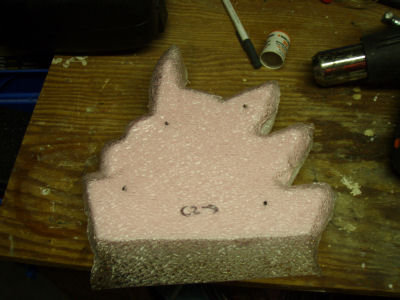 Result of the styrene melted onto the Styrofoam
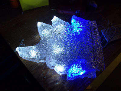 An early test of the blue and white lights inside the styrene panels
The proof of concept looked OK, but there was no way that I could get the styrene to stretch out properly around the Styrofoam forms. Also, the styrene started melting onto the Styrofoam and it all stuck together.
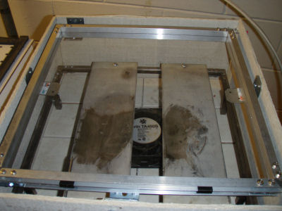
So, I decided to take a cue from the Star Wars armor builders and make my own vacuum forming table. I built the heater with heating elements I found at Ax-Man, metal tubing, and Hardi-Backer board to hold in the heat. I built a small vacuum table (about 15x15 inches) with particle board and dimensional lumber from Home Depot. I nicknamed these two components the “Hibachi from Hell” and the “Suck Box”, respectively.
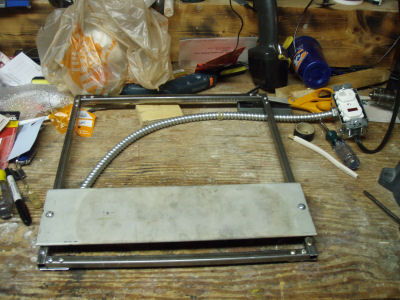 Building the heater with a heating element bolted onto a metal frame
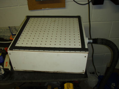 The vacuum table
I then started experimenting with forming and melting acrylic plastic, but that didn’t work right. The acrylic started bubbling up and melting unevenly. Also, it started melting onto the Styrofoam when I formed it.
 The acrylic was already starting to show fine bubbles in it
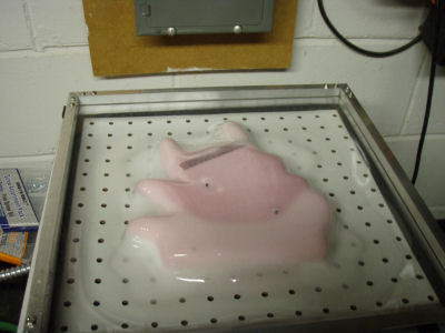 After this experiment, the acrylic was fused to the Styrofoam
So, I called Plastics International, conveniently located just down the street from me, and asked if they had sheet styrene suitable for thermoforming. They suggested PET-G (polyethylene glycol terephthalate, glycol-modified), which is sort of like pop bottle plastic, as being better for thermoforming. So, I gave that a try. I also switched from Styrofoam molds to wooden molds, cut from particle board, so I wouldn’t have to melt plastic into Styrofoam and cut the two apart. I also found that I had to manipulate the plastic to get it to sink deep into the gaps between the spines.
 A sheet of PETG plastic in the heater
 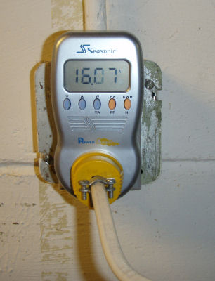 "Vegeta! What does the Power Angel say about his power level?" "It's over 16!"
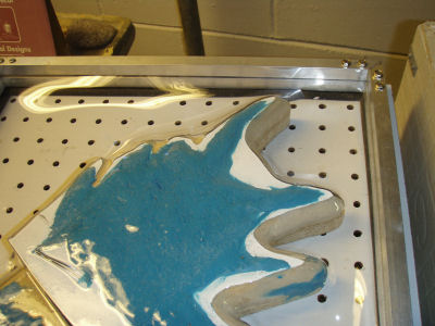 Results of melting the plastic onto a wooden form (with a little blue clay to avoid some voids)
By the way, that power meter is reading 16.07 amps, which is actually more than a 15 amp residential circuit can provide. That’s with two heaters. When I upgraded the Hibachi from Hell to three heaters, I had to plug it into two separate circuits.
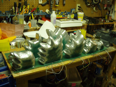
Anyway, to make a long story short, I formed 15 dorsal fins. Each had a left side, a right side, and a center section with the LEDs mounted on a flat piece of plastic. I had the first row of fins completed by the end of November, along with the lighting.
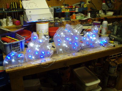 The first row of spines on the workbench, powered up.
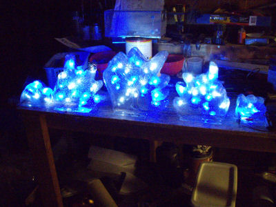 The spines look more impressive with the shop lights off.
I spent part of December airbrushing the paint onto the fins, as well as creating circuitry that would light up the LEDs in a progressive fashion. Instead of turning on all the LEDs in one shot, I used a microcontroller called the BASIC Stamp that can be programmed to run various programs based on input received through pushbuttons or other sensors. Here’s a picture of the BASIC Stamp set up. The outputs from the BASIC Stamp drive six power transistors, which switch on power from a 12-volt battery and power the LEDs.
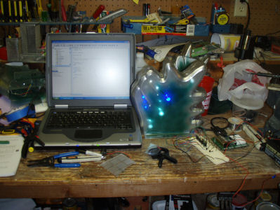
This may have been too much engineering, but hey, it’s cool.
By mid-March, I had the second row of fins painted and mounted to the backing fabric.
Two rows of spines on the backing fabric.
Actually, I think I had the third row of fins done around this time, but I don’t have the pictures handy.